Bringing a new product from a “napkin sketch” to a retail-ready reality is a journey fraught with technical hurdles. In the world of
plastic injection molding, the difference between a successful product launch and a costly production delay often comes down to the initial design phase.
At
Delaney Manufacturing Services, we have spent over 50 years refining the art of
Design for Manufacturability (DFM). We see inventors and established manufacturers alike stumble over the same recurring design pitfalls. These mistakes don’t just affect the look of your part; they lead to structural weaknesses, cosmetic defects like sink marks, and unnecessarily high tooling costs.
To help you navigate your next project, we have compiled the seven most common mistakes in plastic part design and, more importantly, how to solve them before they hit the production floor.
1. Non-Uniform Wall Thickness
The golden rule of injection molding is simple: keep your wall thickness uniform. When a part has thick and thin sections, the plastic cools at different rates. This differential cooling creates internal stresses that lead to
warping,
sink marks, and
voids.
The Fix:
Design your part with a consistent nominal wall thickness. If your design requires varying thicknesses, ensure the transition between thin and thick areas is gradual. Use a taper or a long chamfer to allow the plastic to flow and cool more predictably. If a section needs to be thicker for strength, consider using
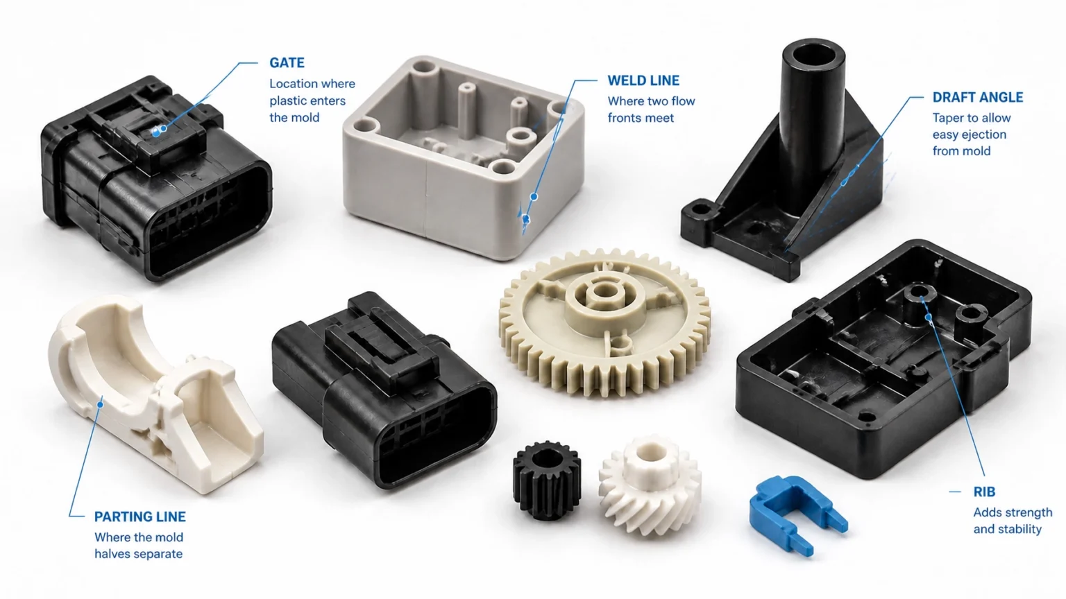
ribs instead of a solid block of plastic.
2. Inadequate Draft Angles
Imagine trying to pull a straight-sided ice cube out of a perfectly square tray. It sticks. In injection molding,
draft is the slight taper applied to the vertical faces of a part. Without it, the vacuum created during cooling causes the part to grip the mold, leading to “drag marks,” scuffing, or even part breakage during ejection.
The Fix:
As a standard rule of thumb, apply a minimum of
1 to 2 degrees of draft to all surfaces parallel to the direction of the mold opening. For parts with textured finishes, you may need as much as 3 to 5 degrees to ensure the part releases cleanly without damaging the surface aesthetics.

3. Sharp Internal Corners
Sharp corners are the primary cause of mechanical failure in plastic parts. They create “stress concentrators”: points where the physical load is magnified, making the part prone to cracking under pressure. Additionally, sharp corners impede the flow of molten resin, leading to air traps and structural weak spots.
The Fix:
Replace sharp corners with
radii and fillets. A rounded corner allows the plastic to flow smoothly and distributes stress across a larger area. For maximum strength, aim for an inside radius that is at least 50% of the adjacent wall thickness, and an outside radius of 150% to maintain a uniform wall.
4. Over-Designing Ribs and Bosses
Ribs are excellent for adding structural rigidity, and bosses are essential for assembly points (like screw holes). However, making them too thick is a common error. If a rib or boss is as thick as the wall it’s attached to, it will pull the material inward as it cools, creating a visible
sink mark on the cosmetic “A-side” of your part.
The Fix:
Follow the 60% rule: keep the thickness of ribs and bosses to approximately
40% to 60% of the thickness of the main wall. This ensures the features are strong enough for their function but thin enough to cool quickly without causing cosmetic deformities.
5. Neglecting Gate Placement
The “gate” is the entry point where molten plastic enters the mold cavity. Poor gate placement can result in unsightly “weld lines” (where two flow fronts meet) or “gate vestige” (a small nub of plastic) in highly visible or structurally critical areas.
The Fix:
Plan your gate placement during the
CAD design phase. Ideally, gates should be located in non-cosmetic areas, such as the inside of a housing or under a label. Strategic placement ensures that any weld lines are pushed to the edges of the part or areas where they won’t compromise the part’s integrity.

6. Creating Impossible Undercuts
An
undercut is any feature (like a side hole or a snap-fit) that prevents the part from being pulled straight out of the mold. While undercuts are often necessary, they require complex mold mechanisms like “slides” or “lifters,” which significantly increase the cost and lead time of your tooling.
The Fix:
Challenge your design to see if the undercut can be eliminated. Often, a small change in the
parting line or the addition of a “shut-off” (a hole through the part) can allow the feature to be molded with a simple straight-pull tool. If an undercut is unavoidable, work with your manufacturing partner to minimize its complexity.
7. Choosing the Wrong Material for the Application
A part designed perfectly for Polypropylene (PP) may fail miserably if molded in Polycarbonate (PC). Every resin has unique shrinkage rates, flow characteristics, and environmental tolerances. Designing a part without a specific material in mind often leads to dimensional inaccuracies and failure in the field.
The Fix:
Select your
plastic material early. Consider the operating environment: Will it be exposed to UV light? High heat? Harsh chemicals? Once the resin is selected, the design must be adjusted to account for that specific material’s shrink rate. At Delaney, we often help clients with
metal-to-plastic conversion, identifying heavy-duty polymers that can outperform traditional metal components at a fraction of the weight and cost.

The Delaney DFM Advantage
Designing for success requires a holistic view of the entire product lifecycle. Many designers focus solely on the “look” of the product, but at
Delaney Manufacturing Services, we focus on how it will be built, assembled, and shipped.
Our
product development services bridge the gap between concept and creation. We offer:
- CAD Design & Prototyping: We use 3D printing to validate designs before cutting steel.
- Tooling Expertise: We handle mold production and management with a focus on longevity and efficiency.
- End-to-End Fulfillment: From plastic injection molding to assembly and drop-shipping, we handle the details so you can focus on growing your business.
Whether you are an entrepreneur with a new invention or an established manufacturer looking for a more reliable production partner, our team is ready to provide the expert guidance needed to avoid these common mistakes.
|
| Images for illustrative purposes. |