In the world of plastic injection molding, the transition from a conceptual CAD model to a physical, high-quality part is rarely a straight line. Many inventors and engineers approach manufacturing with the assumption that a functional 3D design is inherently ready for production. However, without a rigorous
Design for Manufacturability (DFM) review, even the most innovative products can face catastrophic delays and astronomical costs once they reach the tooling stage.
At
Delaney Manufacturing Services, we have spent over 50 years bridging the gap between design and reality. We have seen firsthand how minor adjustments made during the initial development phase can prevent the need for expensive mold modifications, reduce cycle times, and eliminate high scrap rates. DFM is not merely a technical checklist; it is a strategic financial tool that ensures your product is optimized for the physics of the injection molding process.
The Economic Impact of Early DFM
The cost of design changes follows an exponential curve. A modification made during the “napkin sketch” or initial CAD phase costs virtually nothing beyond the engineer’s time. Once a steel mold is cut, however, that same modification can cost thousands: or tens of thousands: of dollars.
When a design is not optimized for manufacturing, the manufacturer often encounters issues such as part warping, sink marks, or difficulty ejecting the part from the mold. These issues necessitate
tooling revisions, which involve precision machining, welding, or even the creation of entirely new mold components. Beyond the direct repair costs, you lose valuable weeks in your production schedule. By investing in a comprehensive DFM review early in the
product development process, you essentially “buy insurance” against these downstream failures.
Critical Technical Features of DFM
To understand how DFM saves money, one must understand the technical requirements of the injection molding process. High-pressure molten plastic behaves according to strict thermodynamic and mechanical laws. Design decisions must align with these laws to ensure a successful “first shot.”
1. The Necessity of Draft Angles
Perhaps the most common oversight in plastic part design is the omission of
draft angles. In injection molding, a “draft” is a slight taper applied to all vertical walls of a part.

As the plastic cools in the mold, it shrinks and grips onto the mold’s internal features (the core). If the walls are perfectly vertical (90 degrees), the friction created during ejection can cause the part to stick, scuff, or even crack. This leads to high scrap rates and potential damage to the mold surface itself.
- Standard Practice: A minimum draft angle of 0.5 to 1.0 degrees is required for most smooth surfaces.
- Textured Surfaces: If your part has a leather-like or matte texture, you may need 3 to 5 degrees of draft to prevent the texture from being “smeared” during ejection.
- Cost Savings: Proper draft angles ensure a clean release every cycle, maximizing production speed and minimizing manual labor required to clear stuck parts.
2. Uniform Wall Thickness and Rib Design
In injection molding, thickness equals time. The thicker a plastic section, the longer it takes to cool. More importantly, non-uniform wall thickness causes the part to cool at different rates, leading to internal stresses that cause
warping and
sink marks (depressions on the surface of the part).

To maintain structural integrity without adding unnecessary bulk, engineers use
ribs. However, rib design is a delicate science:
- The 60% Rule: To prevent sink marks on the opposite side of a cosmetic surface, ribs should generally be no thicker than 50% to 60% of the thickness of the main wall they are attached to.
- Nominal Wall Range: Most successful plastic parts maintain a nominal wall thickness between 1.5mm and 3.0mm.
- Cost Savings: By keeping walls thin and uniform, you reduce the cycle time: the seconds it takes to mold one part. In high-volume production, shaving even two seconds off a cycle can save thousands of dollars in machine time over the life of the project.
3. Radii and Fillets: Reducing Stress Concentrations
Sharp corners are the enemy of durable plastic parts. Not only do they make it difficult for molten plastic to flow into the mold’s extremities, but they also act as
stress concentrators. A part with sharp internal corners is significantly more likely to fail under impact or environmental stress.

Incorporating
radii and fillets allows for a more uniform flow of material and distributes mechanical loads across a larger area.
- Internal Radii: Should be at least 50% of the wall thickness.
- External Radii: Should be roughly 150% of the wall thickness to maintain a consistent wall path around the corner.
- Cost Savings: This design choice reduces the risk of field failures and product recalls, protecting your brand’s reputation and bottom line.
4. Strategic Gate Placement
The
gate is the point where the molten plastic enters the mold cavity. Its location is critical because it dictates how the material fills the part and where the
weld lines (where two flow fronts meet) will appear.

Poor gate placement can lead to “short shots” (where the part doesn’t fill completely) or unsightly blemishes on critical cosmetic surfaces.
- Gate Location: Typically, gates should be located at the thickest section of the part to ensure the cavity packs out properly before the gate freezes.
- Aesthetics: We work with clients to hide gate vestiges in areas that will be covered during assembly or in non-cosmetic locations.
- Cost Savings: Correct gating on the first try prevents the need to “re-gate” the tool, an expensive process that involves plugging existing steel and machining new entry points.
The Delaney Manufacturing Advantage
At
Delaney Manufacturing Services, we do not simply “take orders.” Every project that enters our facility undergoes a comprehensive engineering review. With 50+ years of experience in
custom mold making and production, our team identifies potential DFM issues before the first piece of steel is cut.
Our end-to-end approach means that the same engineers who review your CAD models are the ones overseeing the
injection molding production. This feedback loop ensures that the theoretical benefits of DFM are realized on the production floor. Whether you are an entrepreneur with a new concept or an established OEM looking for a more reliable partner, our goal is the same: to provide a retail-ready product with the lowest possible total cost of ownership.
Conclusion: Designing for Success
Designing for Manufacturability is the difference between a project that launches on time and one that gets bogged down in expensive revisions. By prioritizing draft angles, uniform wall thickness, generous radii, and smart gating, you set the foundation for a high-yield, low-cost production run.
If you are currently developing a plastic product, do not wait until the tooling quote arrives to consider DFM. Contact
Delaney Manufacturing Services today to leverage our expertise and ensure your design is optimized for the highest levels of quality and efficiency.
|
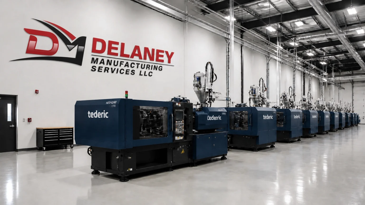
| Images for illustrative purposes. |