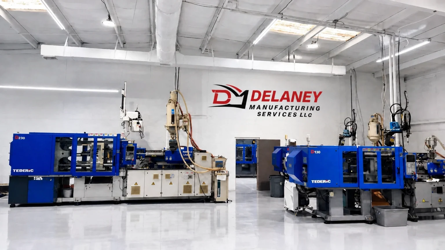
Selecting the correct injection molding machine requires more than matching a mold to a machine’s advertised tonnage.
Projected surface area, cavity pressure, shot size, mold dimensions, and machine capacity must work together to produce consistent parts without unnecessary operating cost.
Clamping force is especially important because it keeps the mold closed while molten resin fills the cavities. If the available force is too low, the mold can separate at the parting line. If the force is excessive, the machine may consume more energy and place unnecessary stress on the mold and tooling.
This guide explains how projected area determines required
injection molding tonnage, how to estimate clamping force, and how Delaney Manufacturing Services evaluates molds for both short-run and high-volume production.
What Is Projected Surface Area in Injection Molding?
In this context, projected surface area does not mean the total three-dimensional surface area of the molded part. It means the part’s
two-dimensional projected “shadow” as viewed from the clamp direction.
The calculation considers the area exposed to injection pressure on the mold’s parting plane. It normally includes:
- The projected area of each molded part
- The projected area of runners
- Sprues, cold wells, and gates where applicable
- Every cavity in the mold
For a simple rectangular part, the projected area is:
Area = Length × Width
For a circular part, the calculation is:
Area = π × radius²
For complex components, the area can be calculated by dividing the projected outline into simpler geometric sections. CAD software and mold-flow analysis can also provide a more precise estimate.

For a multi-cavity mold, the basic calculation is:
Total projected area = (Projected area per part × Number of cavities) + Runner and gate area
The runner system matters because it is also exposed to pressure. Omitting it can produce an undersized tonnage estimate, particularly on molds with large cold runners or multiple cavities.
How Projected Area and Pressure Create Clamping Force
During injection, the screw forces molten plastic into the mold under substantial pressure. That pressure acts across the projected area of the cavities and feed system.
The fundamental relationship is:
Clamping force = Projected area × Cavity pressure
The units must remain consistent. A commonly used shop-floor estimate is:
Clamping force in tons ≈ Projected area in cm² × cavity pressure in bar ÷ 1,000
This is a practical approximation. Actual requirements depend on the resin, mold design, process settings, pressure distribution, and the machine’s method of rating tonnage.
Another widely used approach applies a material-specific tonnage factor:
Required tonnage = Projected area × Tonnage factor × Safety factor
A tonnage factor represents the approximate clamping force required per unit of projected area. Lower-pressure materials such as polypropylene and polyethylene generally require less force than engineering resins, glass-filled materials, or parts with restrictive flow paths.
The most reliable estimate should use available material data, mold-flow results, cavity-pressure measurements, and the experience of the molding engineer. General formulas are useful for machine screening, but they do not replace a complete process review.
Worked Example: Estimating Injection Molding Tonnage
Consider a two-cavity mold producing a rectangular component.
- Projected area per cavity: 140 cm²
- Number of cavities: 2
- Projected runner and gate area: 70 cm²
- Estimated cavity pressure: 350 bar
First, calculate the total projected area:
(140 cm² × 2) + 70 cm² = 350 cm²
Next, apply the pressure-based formula:
350 cm² × 350 bar ÷ 1,000 = 122.5 tons
This is the estimated force required to resist the injection pressure. A safety margin is then added to account for process variation, pressure peaks, material changes, and normal machine operating conditions.
With a 15 percent margin:
122.5 tons × 1.15 = 140.9 tons
A machine rated at approximately
150 tons may therefore be an appropriate starting point, provided it also meets the mold’s shot-size, platen, tie-bar, daylight, and injection-pressure requirements.

This example demonstrates why machine selection should not rely on the part’s weight alone. A relatively light part can still require significant tonnage if it has a broad projected area, a long flow path, high cavity pressure, or multiple cavities.
What Happens When There Is Too Little Tonnage?
If injection pressure exceeds the force holding the mold closed, the mold can separate slightly at the parting line. This condition creates several quality and tooling problems.
Flash
The most visible result is
flash, which is a thin, unwanted layer of plastic that escapes between mold components. Flash may appear around the parting line, ejector pins, slides, or inserts.
Increasing clamp force may temporarily reduce the symptom, but flash can also indicate:
- A damaged or contaminated parting line
- Mold misalignment
- Uneven clamp distribution
- Excessive injection pressure
- Worn tooling components
Parting-Line Damage
Repeated mold separation can damage shutoffs, parting-line steel, slides, and other precision surfaces. Once these areas wear, the mold may require polishing, rework, or replacement of damaged components.
Inconsistent Dimensions
Mold separation changes the cavity geometry during filling and packing. The result can be inconsistent wall dimensions, variable part weight, poor flatness, and dimensional drift from cavity to cavity.
Low tonnage can also force a processor to reduce injection pressure or speed. That may prevent flash but create short shots, sink, weld-line weakness, or incomplete packing.
Why Excessive Tonnage Is Also a Problem
More clamping force is not automatically better. Running a mold at substantially higher tonnage than necessary can create its own problems.
- Higher energy consumption: The machine may use more hydraulic or electrical energy to maintain excessive force.
- Increased mold wear: High clamp loads can stress parting lines, inserts, guide components, and mold plates.
- Greater risk of mold deflection: Excessive force can distort plates or create uneven loading.
- Higher operating cost: A larger machine may have a higher purchase price, larger footprint, and greater maintenance requirements.
- Reduced flexibility: Oversized machines may not offer the best injection-unit range for the required shot size.
The objective is not to select the largest machine available. The objective is to select the
smallest machine that safely satisfies the process requirements with an appropriate operating margin.
Factors That Change the Required Tonnage
Projected area provides the foundation, but several factors influence the final machine recommendation.
Resin Type
Material viscosity, shrinkage, reinforcement, and processing temperature affect pressure requirements. Glass-filled nylon, polycarbonate, acetal, and other engineering materials may require more pressure than commodity resins.
Cavity Count
Adding cavities increases projected area and shot size. A four-cavity mold may require approximately twice the clamping force of a two-cavity mold with the same part geometry, although runner design and pressure distribution also matter.
Flow Length and Wall Thickness
Long flow paths and thin walls increase resistance to flow. The machine may need higher injection pressure to fill the mold, which increases the required clamping force.
Mold Design
Runner layout, gate type, venting, slides, lifters, inserts, and parting-line design can all affect pressure and clamp requirements. Poor venting, for example, may increase filling pressure and create quality defects that are incorrectly attributed to tonnage.
Safety Margin
A practical safety margin often falls in the range of
10 to 20 percent, but the appropriate value depends on the accuracy of the pressure estimate and the stability of the process. A validated mold-flow analysis may justify a tighter range than an early-stage estimate based only on geometry.
Tonnage Is Only One Part of Machine Selection
A machine can have adequate clamping force and still be unsuitable for a mold. The mold and machine must be compatible in several dimensions and capacities.
Shot Size and Injection Capacity
The machine must deliver enough material for the complete shot:
Shot size = Total part weight + runner weight
The selected shot should not operate at the extreme limits of the injection unit. A reasonable level of barrel utilization helps maintain melt quality and residence-time control. Resin density also matters because the same volume of different materials produces different weights.
For more information about this related selection issue, see Delaney’s guide to
plastic injection molding.
Mold Dimensions and Tie-Bar Spacing
The mold must fit between the machine’s tie bars and onto the platens. Important checks include:
- Mold width and height
- Tie-bar spacing
- Platen dimensions
- Maximum and minimum mold thickness
- Available daylight
- Mold opening stroke
- Ejector stroke and pattern
- Locating-ring and sprue-bushing compatibility
These mechanical requirements can eliminate a machine even when its tonnage rating is correct.
Available Machine Capacity
The selected machine should provide adequate injection pressure, injection rate, screw recovery, cooling connections, automation interfaces, and process-control capability. For high-volume work, repeatability and cycle-time performance are as important as the nominal tonnage rating.
How Delaney Manufacturing Services Selects the Right Machine
At Delaney Manufacturing Services, machine selection begins with the complete mold and part requirements rather than a single tonnage number. Our team reviews the part geometry, projected area, cavity count, runner system, resin, shot weight, mold dimensions, and expected production volume.
We then match the mold to available equipment and verify that the machine can provide:
- Sufficient clamping force without excessive overcapacity
- Appropriate shot size and barrel utilization
- Adequate injection pressure and speed
- Compatible tie-bar spacing and platen dimensions
- Reliable operation for the expected cycle and production schedule
For short-run programs, this approach helps avoid unnecessary tooling and machine costs while maintaining dependable quality. For high-volume production, we focus on repeatability, cycle efficiency, automation, preventive maintenance, and long-term mold protection.

With more than
50 years of plastic injection molding experience, Delaney supports projects ranging from early product concepts to established production programs. Our end-to-end capabilities include product development, mold management, injection molding, assembly, packaging, and fulfillment.
We also provide
same-day responses and work with customers regardless of project size. If you need help evaluating a mold, estimating injection molding tonnage, or selecting a machine for custom production, contact
Delaney Manufacturing Services to discuss your requirements.
|
| Images for illustrative purposes. |